Next: Beamline Specific Code by Up: Online -tki Previous: The MCA Widget Contents Index
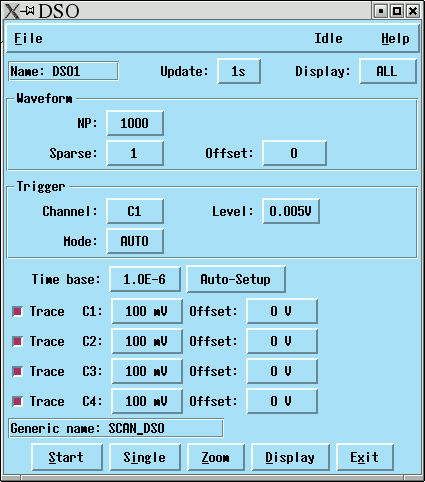
Figure 13.1 shows the DSO menu. It is invoked by a button of the toplevel widget. This button is displayed, if a DSO has been defined.
Here is an explanation of the elements:
| Update: The refresh interval. | |||
| Display: Selects the displayed channels. | |||
The Trigger frame
| |||
The Trigger frame
| |||
| Time base: The DSO samples at a constant rate, depending on the module type. The time base is the time interval that corresponds to 1cm on the oscilloscope screen. | |||
| Auto-Setup: Sends the Auto-Setup command to the DSO. The time base, vertical gain, vertical offset and trigger conditions are automatically adjusted. | |||
| Trace C1: Enables channel 1, selectes the voltage range (vertical gain) and the offset. | |||
| Generic name: Specifies the generic part of the file name that is
used when the data are written to a disk file.
|