Next: Diffractometer, Tango Up: Hardware Previous: DC_Motor Contents Index
Dual gate generator: 2 channel NIM outputs (-0.8V, 50 Ohm), internal clock 1 MHz, 32 bit register, external clock: TTL input, DGG2: 1 MHz TTL clock output (50 Ohm), can be divided, diver reset by start_timer() call.
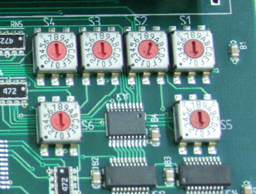
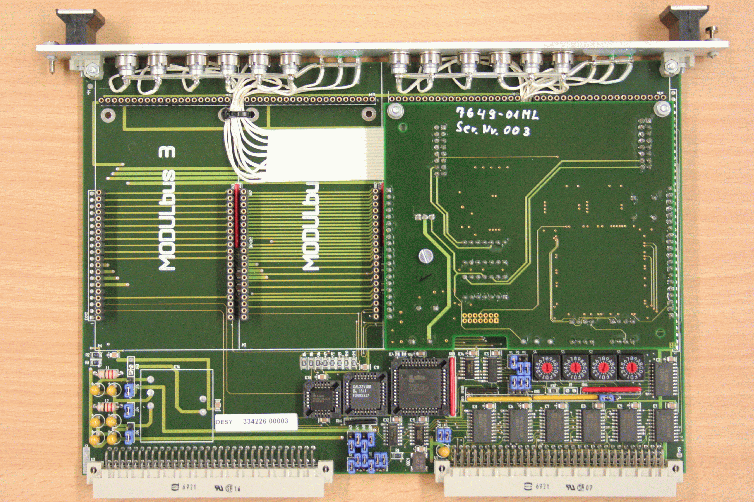
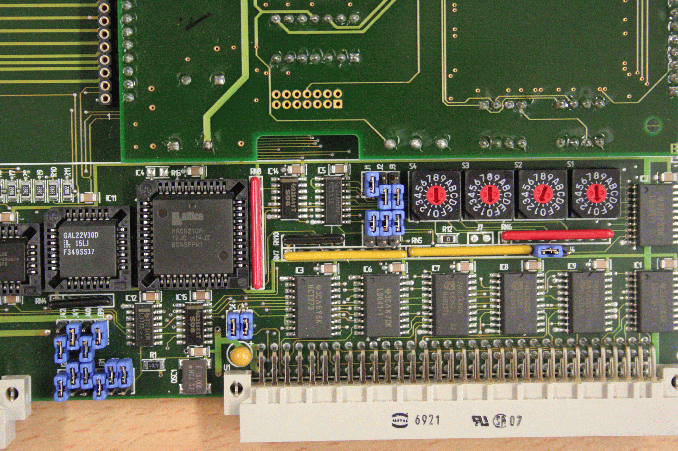
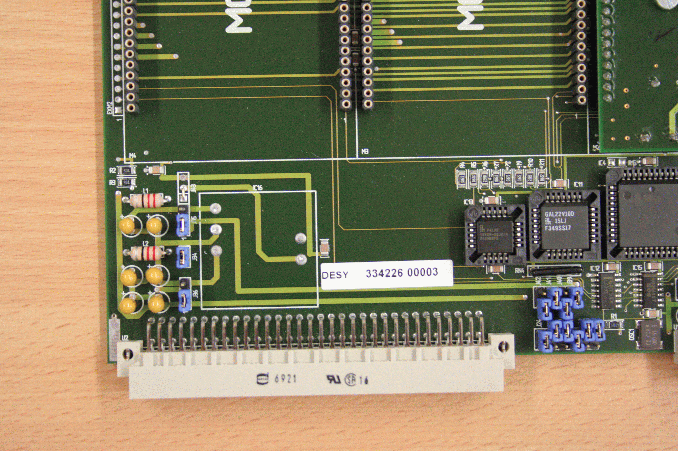
VME: A16D16 (DGG)/ A24D16 (DGG2) 2K at 0x1000 (2k aligned). The rotary switches ( VME connectors point downwards): 0010 (the coding 0x1000). The adress of the second device is 0x1800, the switches (s4, s3, s2, s1) = ( 0, 0, 1, 8).
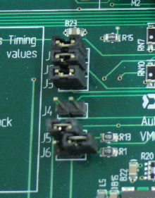
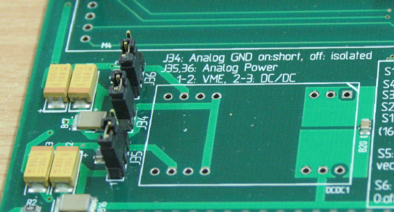
The jumpers (DGG): J36 1, J34 1, J35 1, J42-39 0101, J24-33 100100, J5-5 11, J8-10 010, J1-3 100, J4 right.
The jumpers (DGG2): J36 1, J34 1, J35 1, J42-39 0101, J24-33 100100, J5-5 11, J8-10 000, J1-3 100, J4 left.
The DGG can be operated in the preset mode with wc(), rc(), wft() and resco() (NOT resaco()). Spock: 'ascan exp_dmy01 0 1 10 -0.123' to selects 123000 monitor counts.
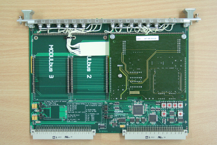
DGG2: After power-on the yellow LEDs should be active, indicating that the FPGA state is ok.
DGG2 power requirements: 5V.
A DGG2 board is introduced to Online by:
define/dev=timer/mod=dgg2/base=0x1000/vector=0/chan=0 t1
define/dev=timer/mod=dgg2/base=0x1000/vector=0/chan=1 t2
Tango (/online_dir/online.xml):
<hw>
... other devices
<device>
 <name>exp_t01</name>
 <type>timer</type>
 <module>dgg2</module>
 <device>p09/timer/exp.01</device>
 <control>tango</control>
 <hostname>haso107tk:10000</hostname>
</device>
<device>
 <name>exp_t02</name>
 <type>timer</type>
 <module>dgg2</module>
 <device>p09/timer/exp.02</device>
 <control>tango</control>
 <hostname>haso107tk:10000</hostname>
</device>
</hw>
A DGG2 can easily be tested with the SIS3820 counter. The procedure is described in 53.
The following figures show the configuration of the DGG2 VME board.