Next: VHQ205L Up: Hardware Previous: VDOT96 (Janz) Contents Index
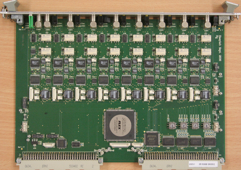
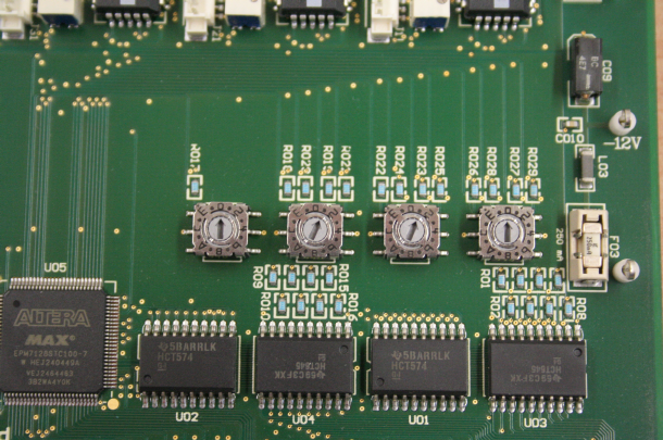
ADC module: 8 analog inputs, NIM gate input, VME A24D16, 80B at 0x011000 (default). Rotary switches: 0110 (The most significant switch is right, if the VME connectors are pointing downwards). The figures 76.1 and 76.2 show the board with the default base address. A second device can be installed with 0x12000 (left '1' to '2').
The power requirements are: 2A at 5V, 250 mA at 12V, 250 mA at -12V.
The device is operated as follows: The NIM gate signal of a DGG2 (or so) is fed into GATE input of the module.
Tango: A VFCADC board is introduced to Online by (/online_dir/online.xml):
<hw>
... other devices
<device>
 <name>exp_vfc01</name>
 <type>adc</type>
 <module>vfcadc</module>
 <device>p09/vfc/exp.01</device>
 <control>tango</control>
 <hostname>haspp09:10000</hostname>
</device>
...
 <name>exp_vfc08</name>
 <type>adc</type>
 <module>vfcadc</module>
 <device>p09/vfc/exp.08</device>
 <control>tango</control>
 <hostname>haspp09:10000</hostname>
</device>
</hw>
For newly created devices make sure that the following attributes are set to default values:
gain == 1
offset == 0
polarity == 1
The command
/usr/lib/tango/fsectools/setVFCADCAttr.py -s
sets gain, offset and polarity for all devices to the default values.
For NON-TANGO:
define/dev=adc/mod=vfcadc/base=0x011000/vector=0/chan=0 vfc1
define/dev=adc/mod=vfcadc/base=0x011000/vector=0/chan=1 vfc2
define/dev=adc/mod=vfcadc/base=0x011000/vector=0/chan=2 vfc3
define/dev=adc/mod=vfcadc/base=0x011000/vector=0/chan=3 vfc4
define/dev=adc/mod=vfcadc/base=0x011000/vector=0/chan=4 vfc5
define/dev=adc/mod=vfcadc/base=0x011000/vector=0/chan=5 vfc6
define/dev=adc/mod=vfcadc/base=0x011000/vector=0/chan=6 vfc7
define/dev=adc/mod=vfcadc/base=0x011000/vector=0/chan=7 vfc8
The module has adjustable gain, offset and polarity:
!
! gain, aliases: gag() and sag()
!
* = get_adc_gain(vfc1)
set_adc_gain(vfc1) = 2
!
! offset, aliases: gao() and sao()
!
* = get_adc_offset(vfc1)
set_adc_offset( vfc1) = 2
!
! polarity, can be +1 or -1
!
* = get_adc_polarity(vfc1)
set_adc_polarity( vfc1) = 1
Make sure that gain, offset and polarity are set correctly. Otherwise the module may produce unexpected results.
The module measures the external gate length with an internal MHz clock to do the gain and offset corrections. The VFCADC is operated using the following functions:
* = reset_counter( vfc1)
* = reset_all_counters()
* = read_counter( vfc1)
* = read_adc( vfc1)
The function read_adc() returns a true voltage value. Gain and offset are corrected and also the sample time.
The function read_counter() returns a count rate. Gain and offset are corrected but the count rate is proportional to the sample time. Here is an example:
!
! set a DAC which is connected to channel 1 to 5 volts
!
sdv(dac1) = 5
!
! reset the channel
!
* = reset_counter( vfc1)
!
! start-and-wait-for-timer: 0.1s
!
sawft(t1) = 0.1

* = read_adc(vfc1)
! -> 4.994349
* = read_counter(vfc1)
! -> 49941

* = reset_counter( vfc1)
!
! start-and-wait-for-timer: 1s
!
sawft(t1) = 1

* = read_adc(vfc1)
! -> 4.994427
* = read_counter(vfc1)
! -> 499431
We have two measurements, the first uses a sample time of 0.1 s, the second of 1s. Notice that in both cases read_adc() returns the value of about 5V, independent of the sample time. In contrast, read_counter() returns a value that is proportional to the sample time. This behaviour has been implemented to make this module compatibel with counters.