Next: Check-motor-registers, cmr Up: Hardware Previous: NIGPIB (PCI-GPIB Interface, National Contents Index
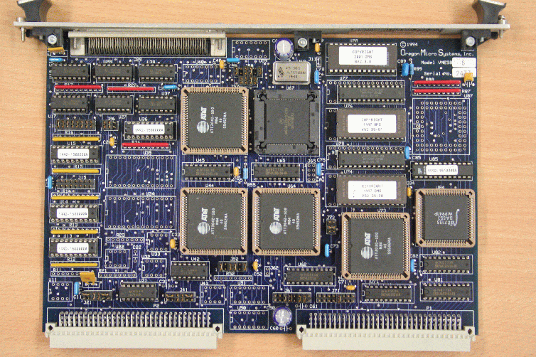
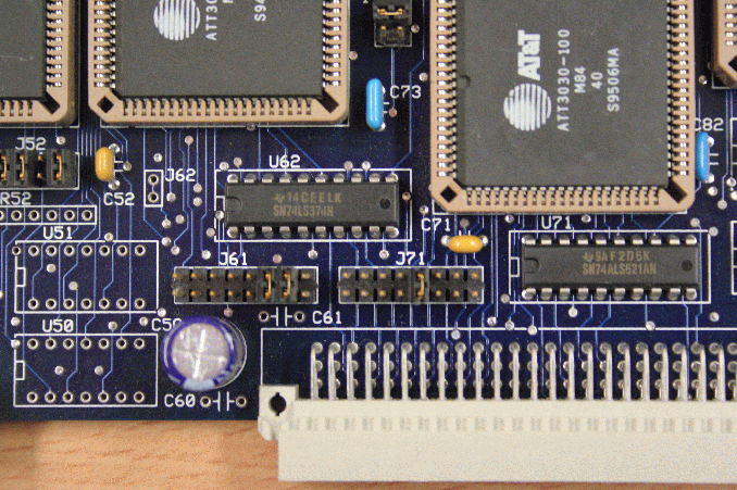
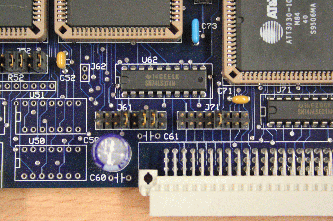
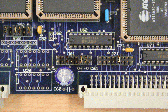
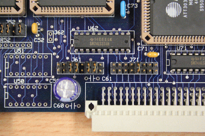
VME motor controller: 8 motors per module. OMS58 selects the stepping motor, OMS58S the servo motor. VME: A16D16/A16D8 4k at 0xf000, 0xe000, .... The step position ranges from -33500000 to 33500000. Jumpers (VME connectors point downwards): J61 00000110 (A15-A12, AM0, AM1, AM4,AM5), J71 00001000, J52 101101, J73 010, J15 00000000 (limit polarity, test mode 11111111), J16 11111111, J26 110, J58 101101, J21 ..11.. ('..' means that the jumper connects the upper pins of adjacent pin pairs), J41 ..11.., J57 1111. The leftmost 4 pin pairs of J61 select the base address. Open jumpers mean '1'. The board is delivered with 0000 (no jumpers set) which translates to 0xf000. This is used by MOT1 - MOT8. The configuration 0001 ( jumper no. 4 set) translates to 0xe000, 0010 to 0xd000, etc.
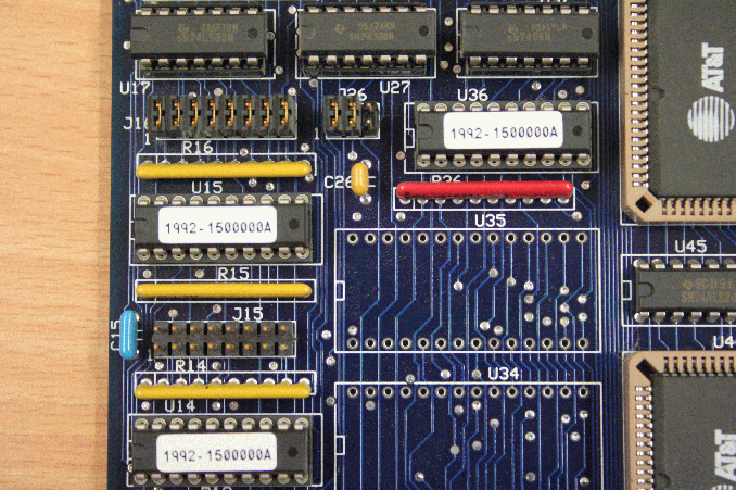
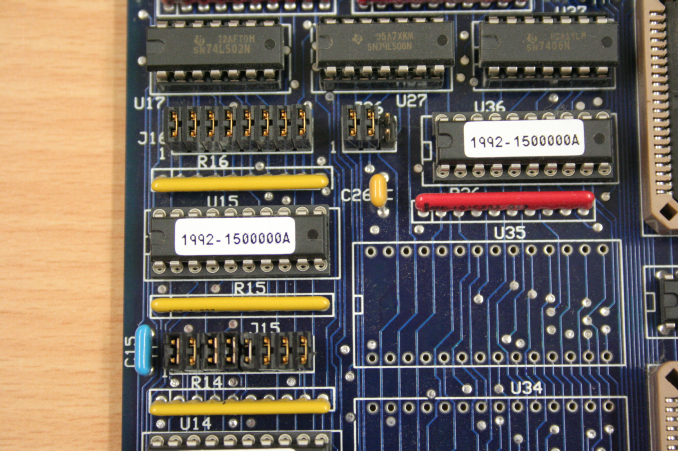
Figure 35.1 shows an OMS VME58 board configured for MOT1 - MOT8 (base 0xf000). The following figures (35.2, 35.3, 35.4, 35.5) show the base address selection for (MOT1-MOT8), (MOT9-MOT16), (MOT17-MOT24), (MOT25-MOT32).
Figures 35.6 and 35.7 show the limit switch polarity selection for the exeperiment and the test setup.
Power requirements: 1.75 A at 5V.
Stepping motors are introduced to Online by:
define/dev=stepping_motor/mod=oms58/base=0xf000/vec=0x0/chan=0 mot1
define/dev=stepping_motor/mod=oms58/base=0xf000/vec=0x0/chan=1 mot2
define/dev=stepping_motor/mod=oms58/base=0xf000/vec=0x0/chan=2 mot3
define/dev=stepping_motor/mod=oms58/base=0xf000/vec=0x0/chan=3 mot4
define/dev=stepping_motor/mod=oms58/base=0xf000/vec=0x0/chan=4 mot5
define/dev=stepping_motor/mod=oms58/base=0xf000/vec=0x0/chan=5 mot6
define/dev=stepping_motor/mod=oms58/base=0xf000/vec=0x0/chan=6 mot7
define/dev=stepping_motor/mod=oms58/base=0xf000/vec=0x0/chan=7 mot8
define/dev=stepping_motor/mod=oms58/base=0xe000/vec=0x0/chan=0 mot9
...
define/dev=stepping_motor/mod=oms58/base=0xd000/vec=0x0/chan=0 mot17
...
define/dev=stepping_motor/mod=oms58/base=0xc000/vec=0x0/chan=0 mot25
...
define/dev=stepping_motor/mod=oms58/base=0xb000/vec=0x0/chan=0 mot33
...
define/dev=stepping_motor/mod=oms58/base=0xa000/vec=0x0/chan=0 mot41
...
define/dev=stepping_motor/mod=oms58/base=0x9000/vec=0x0/chan=0 mot49
...
define/dev=stepping_motor/mod=oms58/base=0x8000/vec=0x0/chan=0 mot57
...
define/dev=stepping_motor/mod=oms58/base=0x7000/vec=0x0/chan=0 mot65
...
Servo motors are introduced by:
define/dev=stepping_motor/mod=oms58s/base=0xf000/vec=0x0/chan=0 mot1
define/dev=stepping_motor/mod=oms58s/base=0xf000/vec=0x0/chan=1 mot2