Next: 'Prepare Regions' Menu Up: Scans Previous: Scans Contents Index
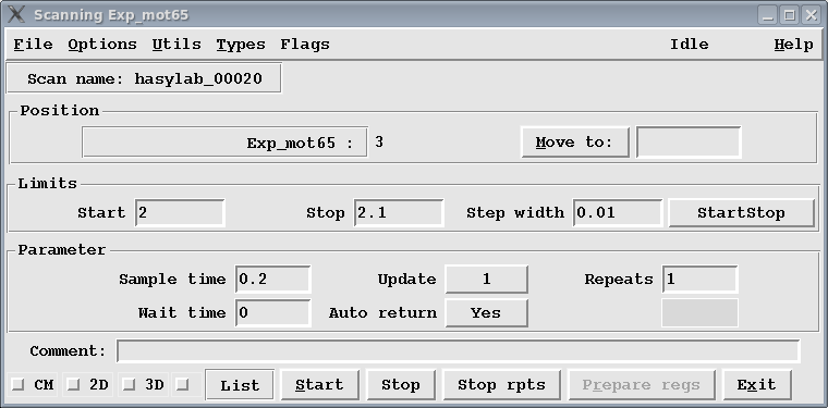
Figure 7.1 displays the Scan widget.
The explanation of the elements:
| Scan name: Scan names are composed of a generic part (prefix) and a combination of numbers and letters that make the name unique. The generic part of the scan name is specified by the user. It can be changed by clicking into the Scan name widget. | ||||||||||||
| Position frame
| ||||||||||||
| Limits frame
| ||||||||||||
| Parameter frame
| ||||||||||||
| Comment: The comment line is displayed on the graphics screen and stored in the output file. | ||||||||||||
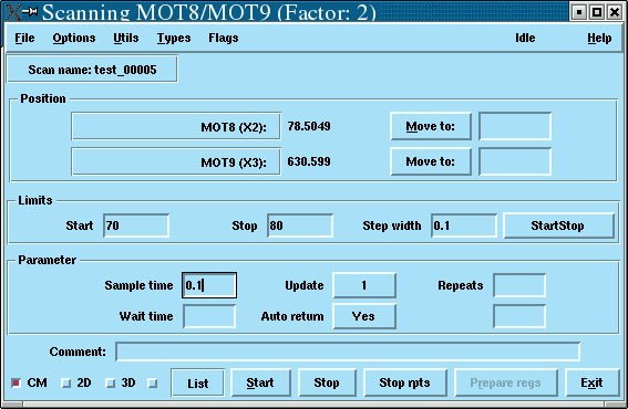
| CM: This checkbutton selects the combined move mode, see figure (7.2). The scan limits are supplied for one motor, the other motor follows. There is a factor between the two scan ranges: CM-factor. This factor can be changed in the options menu (7.8). | ||||||||||||
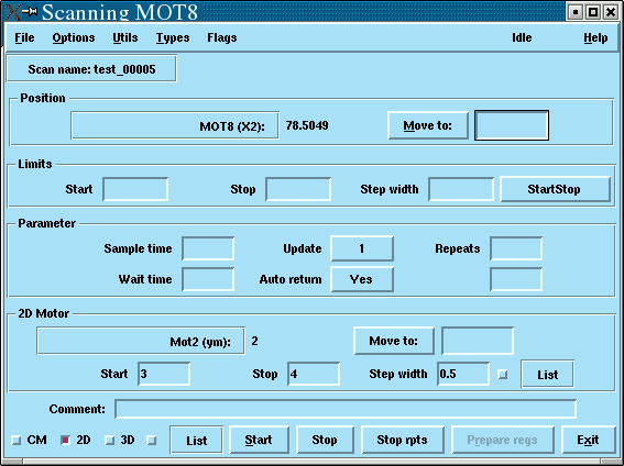
| 2D: Selects a 2d scan, see figure (7.3). The limits of the outer loop motor can be specified in terms of start, stop and step width or as a list of positions. A file <scanName>.log is created and contains log information about the scan. | ||||||||||||
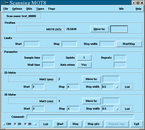
| 3D: Selects a 3d scan, see figure (7.4). The limits of the outer loop motor can be specified in terms of start, stop and step width or as a list of positions. A file <scanName>.log is created and contains log information about the scan. | ||||||||||||
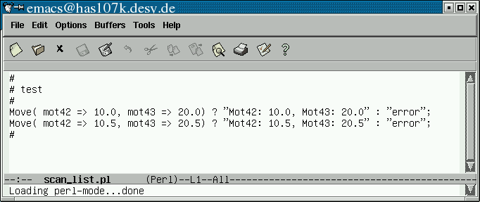
| List: The outer loop is specified by a list of commands. That means, before an inner loop scan is started, Online executes a command from the list. Figure 7.5 shows an example for such a list. Notice that the return string 'error' indicates a failure and interrupts the procedure. The list mode can be used with 1D and 2D scans, including CM option. A file <scanName>.log is created and contains log information about the scan. | ||||||||||||
| Start: Starts a scan. | ||||||||||||
| Stop: Stops all moves and stop the scan. Pressing the <esc> key has the same effect. The stop_function, see 6.11, is also called. | ||||||||||||
| Stop rpts: For repeated scans: make this sweep the final sweep.
|